Originally written 11/24/2002
Later Additions (5/4/03)(11/6/13) (Hello to all my CCNA-Wireless classmates)
11/24/2002
I just took apart and analyzed a Dlink DWL-900AP+
This is one of the new so-called 22MBb access points. Originally costing $119.00 at Micro Center, they have been seen on the web for as low as $85.00.
There's also an occasional rebate
D-Link Manufacturer's data is located at (link is now dead):
http://www.dlink.com/products/digitalHome/wireless/11b+/dwl900ap+/
This unit can:
1. Act as an access point
2. Act as a client to an access point. I Tested with a Linksys and a Cisco 340 AP
3. Act as a bridge
4. Act as a repeater !!!!!! I tried it by repeating one of our Atlanta Freenet Cisco nodes.
5. Work in a Point-to-Multpoint bridge scheme.
The repeater and client modes open some INTERESTING possibilities! All it needs to know is the remote unit's MAC address.
There's a site survey mode- just turn it on and it detects other networks. Select the other network you want to access from a menu. It even automatically sets your SSID to that of the other network
According to D-Link, the repeater mode is not "supported", because it isn't part of the WiFi certification. They claim that it (and the client mode) only work with certain other D-Link units. I know that not to be true! Please note that the repeater mode did not appear on the DWL900AP+ menu until after I had updated firmware to Version 2.2 (available on the D-Link website).
One major downer: The site survey mode (and the AP itself) have no feedback to show the quantity/quality of signal from the other systems. A little graph or at least a number would be great. The log page does show associations and disassociations, though.
Other Interesting Features:
Very small- not much larger than a pack of cigarettes.
15dbm (30 mw) power output
1 external antenna (reverse sex SMA - removable) on the outside of the case and one 1/4 wave antenna INSIDE CASE.
Has PC card inside with 2 antenna ports that are VERY EASY to solder right to! There are also 2 sets of pads that can accept a chassis mount SMA female. Selecting between these and the solder pads that are currently used is done with the move of a pair of chip capacitors. The wireless card uses the new TI ACX100 chip. It is the same chip used in the DWL650_ PC card.
Older versions of the access point have a hidden weca.htm page in the web interface. It allows power setting as well as the selection of how the antennas are used. The page is located at /weca.htm off of the main menu page.
Here's a shot of the page.

With the January 3rd release of 2.5 firmware release, however, the Antenna selection (Internal ant is LEFT and the External ant is RIGHT) and Power selection (up to 19 dBm now!) are now on the web page configuration pages. There are several other additions, as well as an alleged fix for an SNMP security bug. Its also reported that association to non-Dlink access points is more reliable.
My Testing
Here is what I have done with the unit so far:
I happen to have one of the Atlanta Freenet nodes near my home. The backbone nodes are currently using Cisco 340 Bridges (could have used APs but this is what we had). I used the site survey mode on the Dlink to acquire the Cisco and set it up as a repeater. The DLINK took on the ESSID of ATLANTAFREENET.ORG and repeaterd it over the local area, allowing laptop users to associate and surf.
Next, I got another DWL-900AP+ and put it in a place where it could hear the first one (but not the Atlanta Freenet node). Using the DWL900's site survey mode, I acquired the signal from the other Dlink and began repeating it. Again, laptop users were able to browse and surf.
A friend brought his Linksys router over and we were able to succesfully repeat it with the Dlink as well. I'm sorry but I don't have the model and firmware release of the router handy.
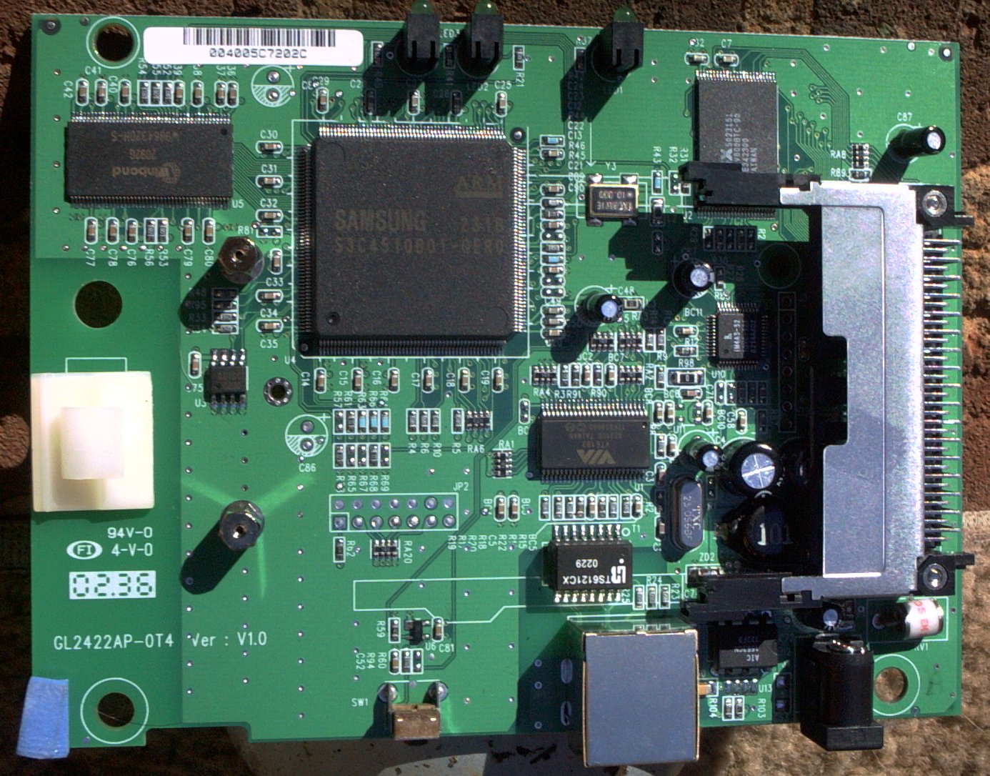
INSIDE THE DWL-900AP+
The Silicon:
CPU: RISC based Samsung S3C4510B01-QERO . It is reported that it will run Linux, but there appears to be no connection facilitated to the UART to allow a console.
Flash memory is made by MX and is an 29LV800BTC-90, same as in the Buffalo Broadstation
Ethernet LAN is handled by a VIA VT6103 chip.
SDRAM is by WINBOND and is a 512 x 4 x 32 arrangement. The part # is W986432DH-5
PLD is a Lattice IM4A3-32 device.
Power is regulated by AIC1563CN Supply voltage: 30V; versatile DC/DC converter. Specs say it takes 3-30 volts in 1.5 amp out with no heat sink
http://doc.analog.com.tw/ap_note_pdf/an004.pdf
Here's some info on the Prism chipset in the wireless card itself http://www.intersil.com/data/an/an1007.pdf
Lastly, there is a chip with the part # AB!5C0230 that I cannot identify. I may have misread the number. It is small surface mount device and reminds me of a PIC.
External connections:
Antenna (see above)
Power (5v at 1.5 amps from a wall wart type switching supply). There is a gas tube protector across the power.Here
is the result of further testing I did to determine an actual operating range of
input voltage that would work..
| Voltage | Current |
| 15 Volts DC | 220-300 ma |
| 12 Volts DC | 260-320 ma | <
| 9 Volts DC | 300-400 ma |
| 7 Volts DC | 390-500 ma |
| 5 Volts DC | 530-680 ma |
| 4.5 Volts DC the AP gets unstable | 550-700 ma |
| and crashes Netstumbler on an Orinoco card |
Power over Ethernet???
I have done it and it worked well!
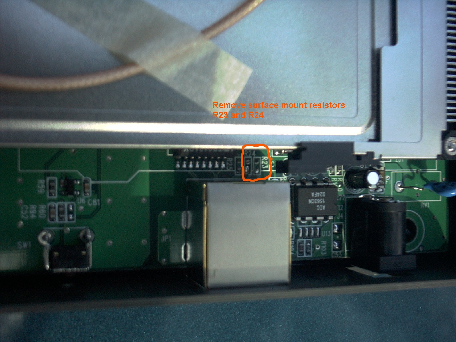
Interesting thing about this Ethernet jack: pins 4-5 and 7-8 are internally
bridged.
In tracing these connections through the access point it appears that, they get connected together through 2 resistors and then disappear under a chip. This may have been done to protect the power supply of an accidentally connected POE source.
Someone recently told me that this is the in the "Ethernet standards"(remember this was written in 2003). I did notice a missing capacitor- think it was C53. It is across the power leads.
I removed the 2 terminating surface resistors. The picture is actually pretty large, so download and save it by right clicking on it.
Then I made a connection from pins 4 and 7 on the Ethernet jack over to the positive and negative pins on the power jack, adding a diode to protect against reverse polarity on the power. (Radio Shack 276-1141). The picture is actually pretty large, so download and save it by right clicking on it.

Now all that's left to do is inject power at the other end of the CAT-5 cable . I made a power injector using the New York City Wireless POE standard. (4-5 Pos 7-8 Negative) for the supply end of the CAT-5 cable. If you check out their site, you will find out lots about POE and they have some slick calculations and drawings as well.
You don't need the power de-injector at the Access Point end, if you made the POE mod I described though. If you try this and damage something, it is your problem- so please don't try unless you have figured it out or you are willing to make the sacrifice!
The unit is up on my tower working today and gives me a 3 mile range to a mobile setup in my car. I am a Ham radio operator and use this under FCC Part 97 rules with my call sign as the SSID. Using the external amp and doing these mods will break the part 15 certification for the rest of you, so don't do it! By the way, here is the Lightning Protection I prefer. ITW-Linx makes awesome stuff for protecting against lightning.
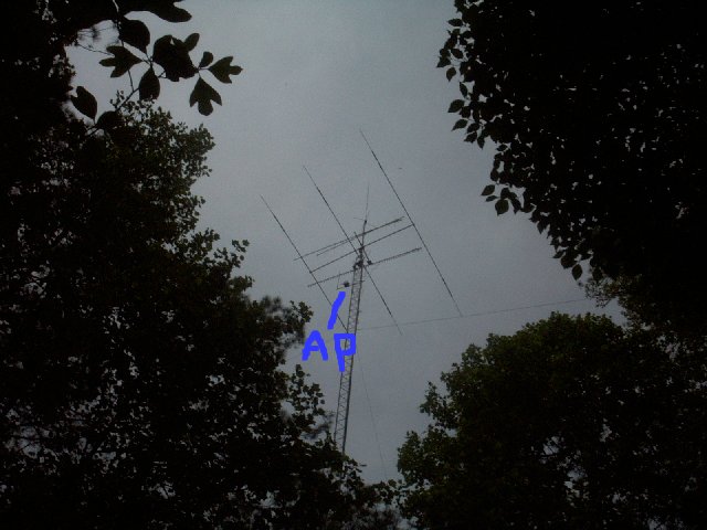
Here's a view of the 120' tower with the AP way up high

Here's me with the system mounted near the ground
A close up of the AP, Amp, and Home Depot 6x6 box
This is during installation, 120' feet in the air
It's a long way down!!
Here are the photos of the inside of the AP.
Top view, card removed
UPDATE 3/15/03
I see many interesting possibilities, and I'd love to see someone hack further on one of these units.
(Why sure, all of us here in Georgia wear overalls 
Amp is from RF Linx

This is a "B" version AP.
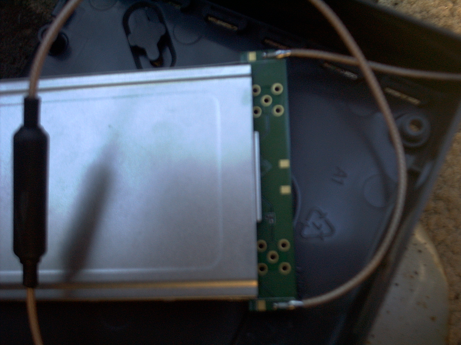
Note that there are both solder pads
as well as places for 2 jacks

Bottom of PC Card
Jan Peman from Sweden writes to say that he has figured out JP2 (the 14 pin connector). He says it appears to be a JTAG connector and that the pinout shows it to be a standard iCARD from iSYSTEM (not TI).
Jan also believes that the 8 pin connector (J3 beneath the pcmcia connector)
might be beginnings of a serial port, but that he hasn't yet been able to check
it out. Thanks Jan for that info, and anyone else has anything to add- please
let me know
Ralph Fowler, N4NEQ
http://www.ralphfowler.com
Check out my Ham Radio Page http://www.bsrg.org